I saw a lot of friends updating their DRL. Some purchased finished product in the store but its quality was not as good as its price: either too powerful or much attenuation. I also wanted to update mine, but I preferred DIY my own LED DRL to get rid of those defects. To keep bulbs off burning out, I decided to purchase LED light bulbs and then DIY a controller based on DRL function. One hand I could guarantee its quality, on the other hand, it helped kill my time.
The function of DRL controller:
The DRL was charged with accumulator. As soon as car engine started, it started to work. When the engine stopped, it would also stop 20 seconds later, and the best thing was the postpone time was adjustable. It was synchronized with turning lights, as well as flashing lights.
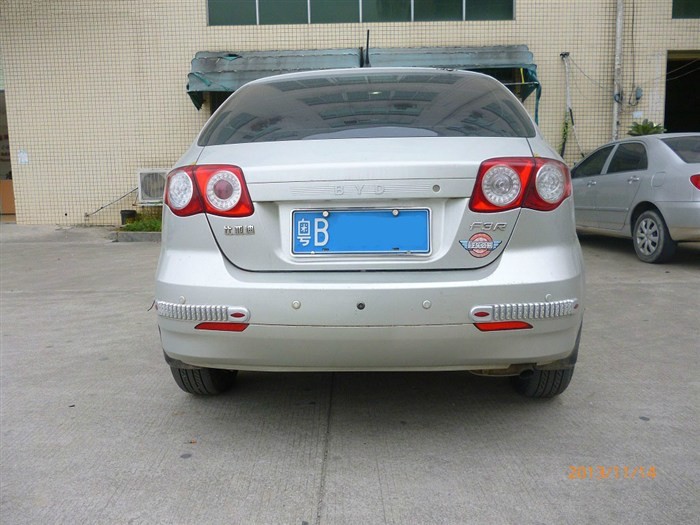
In addition, my reversing lamps did not work very well. Rear camera display did not show very clear even though reversing lamps. So I would DIY new lamps together with DRL.
Those were the details I would like to share with you guys:
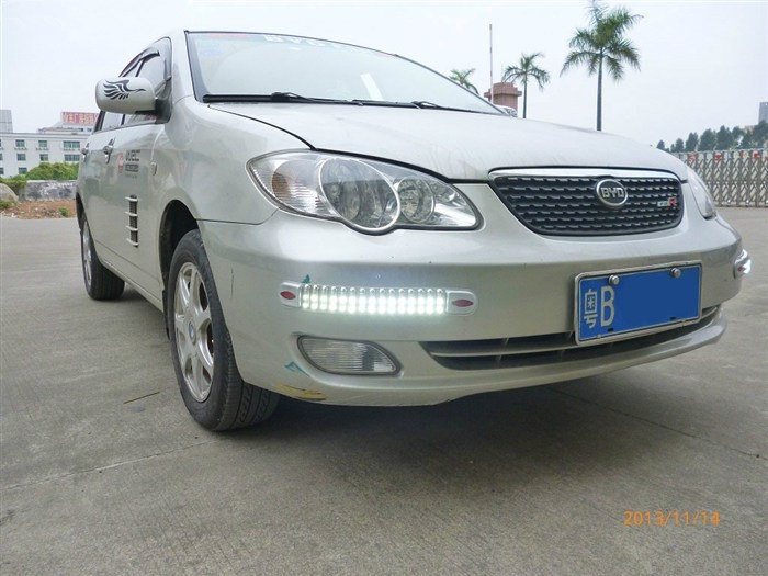
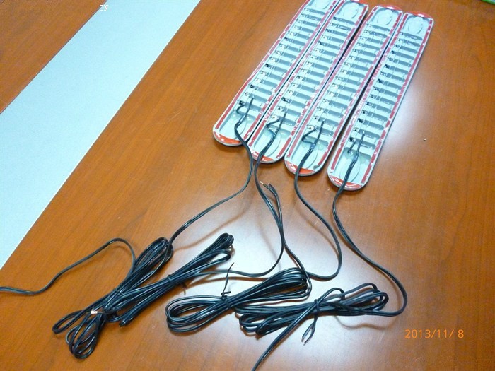
I bought 4 pieces of bumper stickers and they were empty in the middle. Then I could install LED in the middle of those stickers.
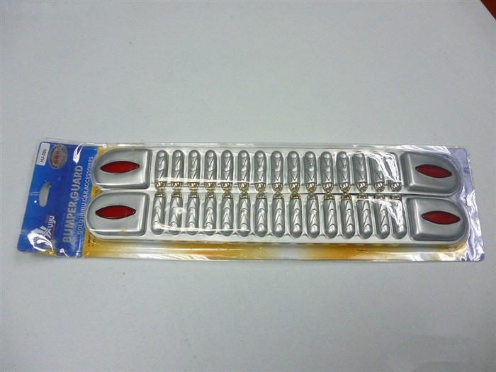
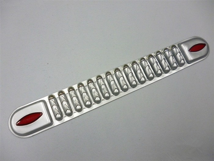

My LED bulbs had a diameter of 5mm. So I only had to drill hole with diameter of 4.5mm. So the LED bulbs could get stuck with bumper.


I got 2 kinds of LEDs from BestLightingBuy: one was for DRL with round heads, the other one was for reversing lamps with straw hat.

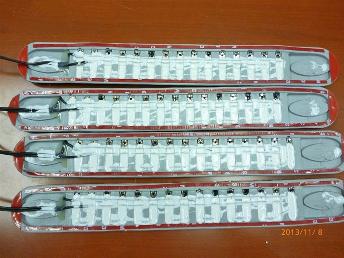
Put the LEDs into bumper strip and connect them with resistance.
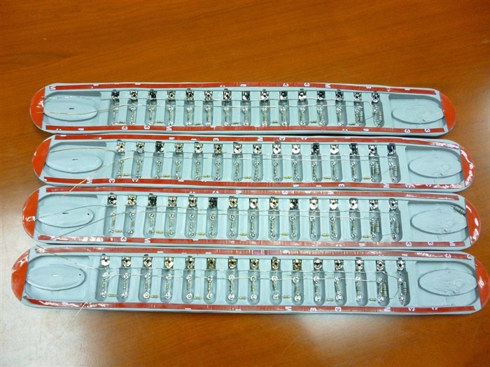
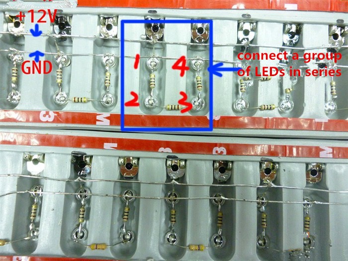
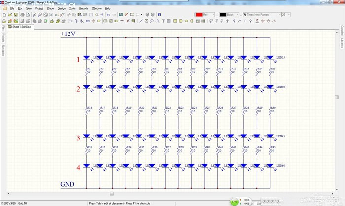
4 LEDs were series connected into a group and then connect those groups in parallel (you would see the connecting sequence was shown in the picture belong). Resistance was 10 ohm each.
Working principle:
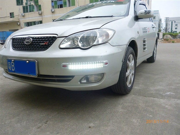
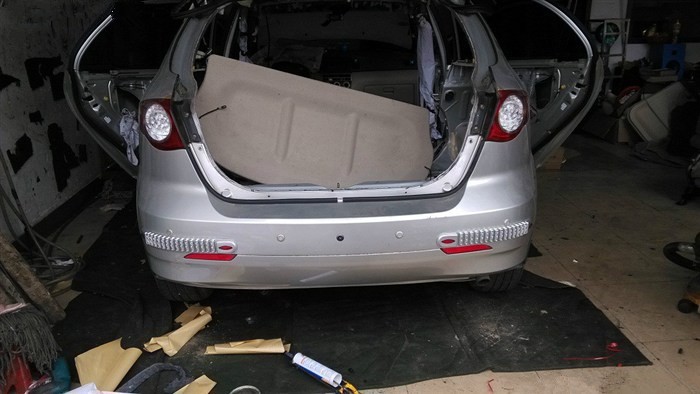
This was how it looked like when finished installation.


Connect with wires.
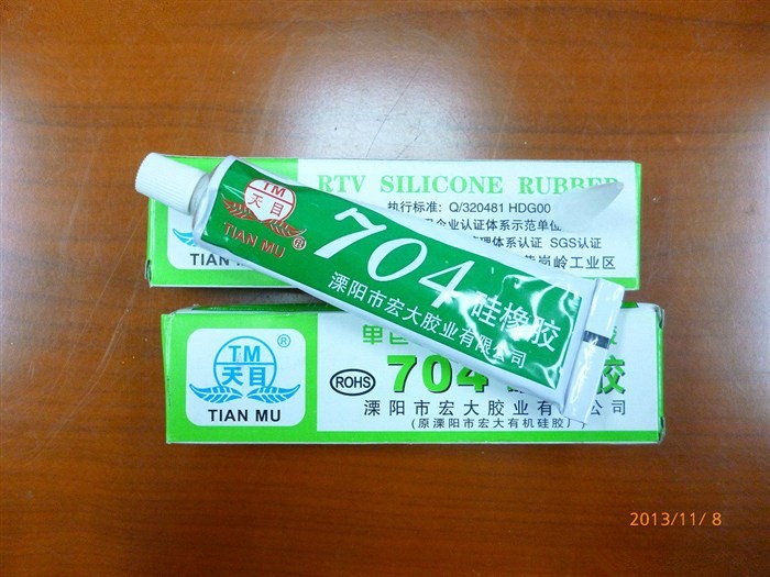
Glue was used for LED sealing and water proof. It was cheap and effective.
A small test for LED strips power: 4 pieces totaled 28W.

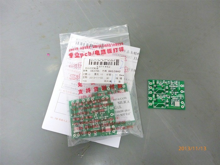
Those were the PCB for DRL controller.
Weld electronic components at PCB.

When finished, put them into box.
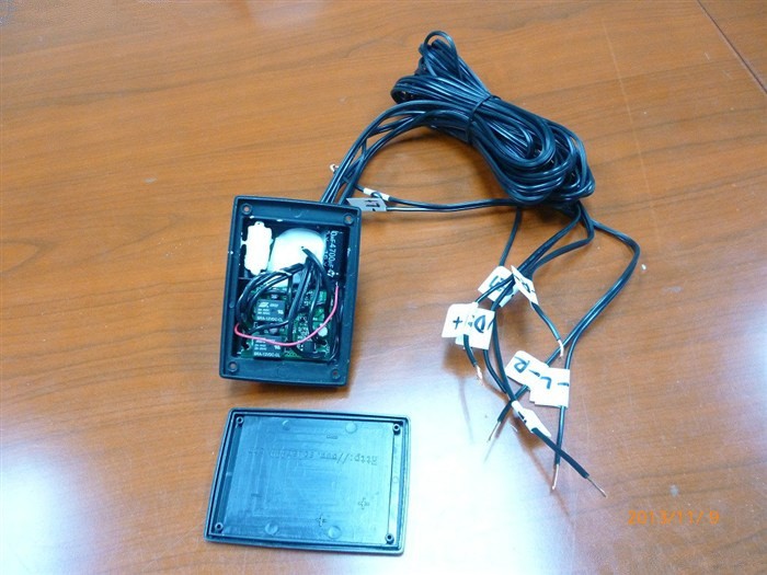
Seal the cover with glue to prevent water.

About installation, I had to drill a small hole in the bumper to lead the wires.
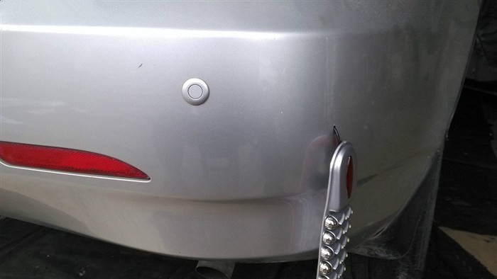
And then put some glue on the bumper stickers.

The wires of new LED reversing lamps were fixed with the old ones. It was simple, anode with red wire and cathode with white.


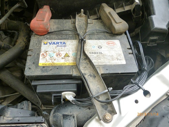
DRL was fixed at accumulator also with glue. And controller power was connected with accumulator anode and cathode.
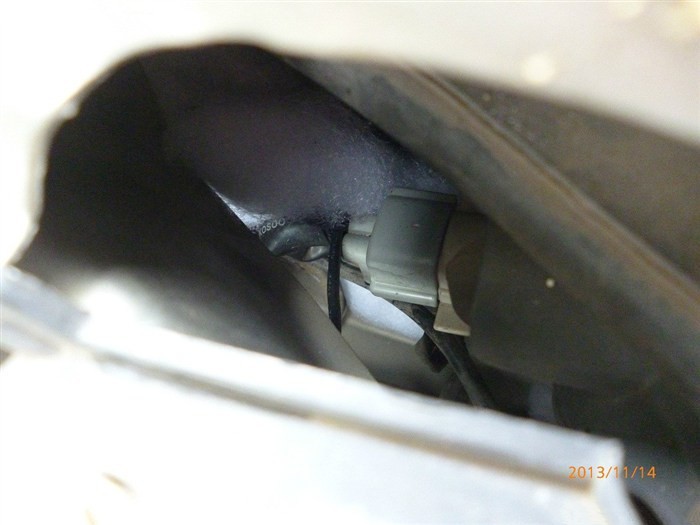
The wires of sparkle lights which were synchronized with turning light were connected with turning lights’ anode and cathode.
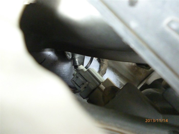
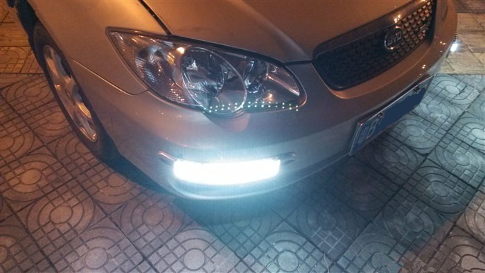
The controller wire was connected with anode of front light, so when I turned on the front light DRL would turn off automatically. And the picture below was how it worked when I started the engine.